Applicable mediumLiquid fluids, slurries, suspensions, high viscosity fluids, etc
Not applicable medium solid
84409900 / 84403377
YS-MFV series V-shaped Coriolis mass flowmeter, with V-shaped internal measuring tube design, is used in all industries as well as process control, trade settlement, loading and unloading systems, difficult to measure fluids (ultra-high temperature, ultra-high pressure, ultra-high viscosity), and laboratory equipment in higher research institutions. Optional tantalum/HC measuring tube, capable of real-time online measurement of highly corrosive media such as nitric acid/sulfuric acid/hydrochloric acid, with high accuracy and good stability, widely used in the chemical and pharmaceutical industries. Simultaneously measure the instantaneous flow rate, cumulative flow rate, temperature, and density of the fluid. High precision standard ± 0.2%, or ± 0.1%. Directly measure fluid quality. The measurement accuracy is not affected by temperature, pressure, density, viscosity, and does not require any compensation conversion. Easy installation, no requirement for front and rear straight pipe sections. When measuring fluid changes, there is no need to recalibrate.

Structure of sensors
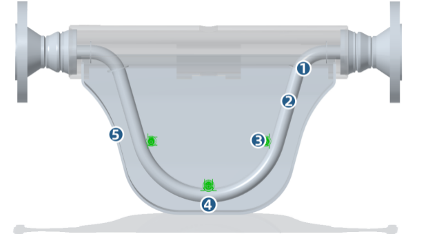
MFV series quality flow meter sensor. It consists of measuring tube, measuring tube driving device, position detector, support structure, temperature sensor, shell and other parts.
① The measuring tube of the supporting structure is fixed on the supporting structure. As the vibration axis of the vibration system, it is also a part of the measurement pipeline.
② The measuring tube (vibrating tube) consists of two parallel bent pipes.
③ The position detector is used to detect twisting changes in the measuring tube.
④ The driving device generates electromagnetic force to drive the measuring tube to vibrate at a frequency close to resonance.
⑤ The shell protects the measuring tube and the driving and detection devices.
Product Features
It can directly measure the mass flow rate of fluid in a closed pipeline and can be used as a high-precision mass flowmeter (which is of great significance for energy measurement and production process control such as chemical reactions);
It can directly measure the working density of the medium and can be used as a high-precision online density meter;
MVDTM measurement technology (multivariate digital processing system) is adopted. The application of MVDTM technology enhances signal filtering, greatly improves the sensitivity and accuracy of signal measurement, accelerates system response time, and makes measurement more reliable;
The adoption of MVDTM measurement technology makes the system composition more flexible and convenient. In many cases, MVD modules and sensors can form a complete flow measurement system without the need to configure a flow converter. For example, CNG, LNG refueling systems, quantitative control systems, flow or density unit parameter measurement systems, etc;
High measurement accuracy, mass flow measurement accuracy can reach 0.1%~0.2%, and density measurement resolution can reach 0.001g/cm ³; Temperature measurement error is less than 0.5 degrees;
● Implementation of density and temperature measurement functions, which can derive medium concentration measurement functions (for two-component media);
The installation requirements are not high (there are no requirements for upstream and downstream straight pipe sections), and the sensor has no mechanical movable parts and operates reliably;
● Wide applicability, the same sensor can be used for multiple media.
Basic parameters of MFV micro bending Coriolis mass flowmeter
Pipeline Diameter | DN2-DN200 | Flow Measurement Accuracy |
Gas:0.5% |
Density Measurement Range | 0<p<5g/cm3 | Density Measurement Accuracy |
|
Temperature Measurement Range | -200℃~350℃ | Temperature Measurement Accuracy | ±1℃ |
Temperature Of The Measured Medium | -50℃~350℃ High temperature customizable | Applicable Ambient Temperature | -40℃~70℃ |
Wetted Material | 316L,304L,HC22, HC276,Ta,904L | Repetitiveness | 0.05% |
Explosion Proof Grade | Ex db ib llcT6 Gb Ex ib tb c T80℃ Db | Protection Level | IP67 |
Work Pressure |
| ||
Output Signal | 4-20mA (dual loop current), 0-10KHZ frequency signal, pulse equivalent signal RS485、HART | ||
Measurement range of MFV micro bending Coriolis mass flowmeter
Model | Nominal Diameter | Flow Range |
MFV-002 | 2 | 0.005t/h~0.1t/h |
MFV-003 | 3 | 0.015t/h~0.3t/h |
MFV-006 | 6 | 0.05t/h~1t/h |
MFV-010 | 10 | 0.09t/h~1.8t/h |
MFV-015 | 15 | 0.15t/h~3t/h |
MFV-020 | 20 | 0.35t/h~7t/h |
MFV-025 | 25 | 0.9t/h~18t/h |
MFV-040 | 40 | 1.35t/h~27t/h |
MFV-050 | 50 | 3t/h~60t/h |
MFV-080 | 80 | 8t/h~160t/h |
MFV-100 | 100 | 18t/h~360t/h |
MFV-150 | 150 | 27.5t/h~550t/h |
MFV-200 | 200 | 55t/h~1100t/h |
Sensor installation
Basic requirements for sensor installation
The installation of MFV Coriolis mass flowmeter sensors should ensure that the flow direction identification of the sensor is consistent with the fluid flow direction.
2. Coriolis mass flowmeter is a flow meter measured based on the principle of measuring tube vibration. Therefore, when installing the sensor, it is necessary to consider providing strong support for the relevant pipelines to avoid vibration of the instrument and related pipelines.
If strong pipeline vibration is unavoidable, it is recommended to use flexible pipes to isolate the pipeline system from instrument sensors.
During installation, the flange faces should be parallel to each other, so that the centers of the two flanges are on the same axis to avoid additional stress.
When measuring liquid flow, the fluid should be directed from bottom to top as much as possible, and the instrument should be avoided from being installed at the highest point of the pipeline to prevent gas accumulation in the pipeline from affecting the normal operation of the instrument.
● Installation method of sensors
To ensure the reliability of the measurement, the installation method of the instrument should consider the following factors:
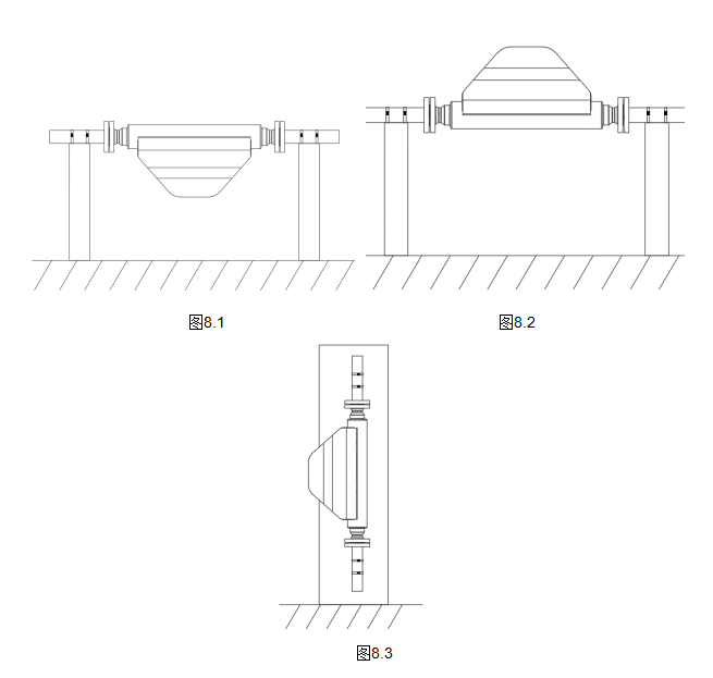
When measuring liquid with a mass flow meter, the housing should be installed downwards. As shown in Figure 8.1, prevent gas from accumulating in the sensor tube.
When measuring gas with a mass flow meter, the housing should be installed upwards, as shown in Figure 8.2, to prevent liquid from accumulating inside the sensor tube.
When the measured medium is a suspension, the sensor should be installed vertically as shown in Figure 8.3. The flow direction of the medium is from bottom to top through the sensor flow.

